Pac Man machine emulator
Here’s a brief description of how the Pac Man hardware works and how (and why) I wrote an emulator to run the original software on a modern computer.
Sometime around 1998 I was working for NEC in the team developing the MMI (a 20th century term for ‘user interface’) for the NEC DB2000 mobile phone. It wasn’t possible for everyone in the team to have access to a device to develop their code on so my job was to maintain a software simulator that allowed the phone code to run on a PC with the behaviour of the hardware (keyboard, screen etc.) recreated in software. The simulator didn’t execute the target bytecode, rather the MMI source code was compiled together with the rest of the simulator code on a PC as a Visual C++ application (Xcode does something similar to this in the iOS simulator). This was deemed good enough to test the interface and the only things to watch out for was the endianness and word length of data types between the two platforms.
The NEC DB2000 was the business
Coincidentally at about the same time development began on the MAME arcade machine emulator. The aim of this project was to preserve classic arcade games by allowing them to be played on modern computers which by this time had become fast enough to run emulations of other computers within themselves. The key difference between MAME and NEC’s phone development platform is that MAME emulates the processor of the target device allowing it to execute the original compiled bytecode.
I’ve been fascinated by the idea of machine emulation ever since and finally got around to having a go at creating an arcade emulator myself. Pac Man is one of my favourite classic arcade games and it’s suitably old and simple that I thought it would be a good starting point. Of course I’m not the first to write a Pac Man emulator so the first thing I did was to research the existing documentation about the original machine architecture and as well as the schematics I also read Chris Lomont’s Pac Man emulation guide. It’s definitely worth a read if you’re interested in all the details of the machine and its comprehensive description of the operation of the Pac Man hardware allowed me to get an emulator up and running in a couple of days. You can download the source code and a compiled .jar of my emulator here.
Here’s an overview of how it works.
The Pac Man System
This sounds brilliant!
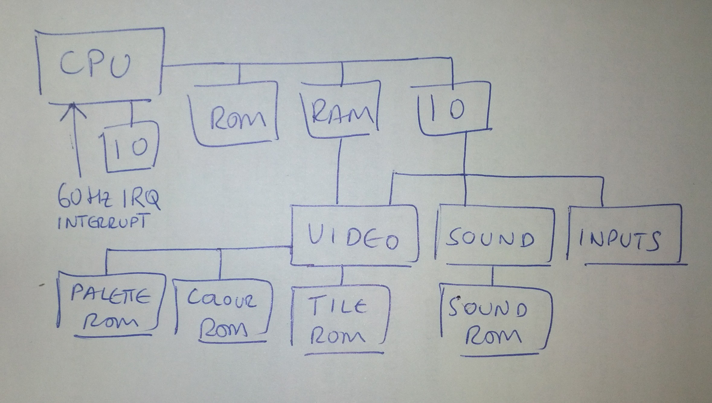
The heart of the Pac Man system is a standard microprocessor system architecture, consisting of a CPU with ROM, RAM and IO accessed via a common address and data bus. There’s two types of IO in the Pac Man system, memory mapped IO and the Z80 peripheral IO. There’s also a 60Hz hardware interrupt which kicks the CPU into updating sound and video:

Here is how the different parts are implemented:
CPU
The machine is based around a z80 8-bit microprocessor. In the emulation this is based on the Java z80-cpu emulator. Additions to that code had to be made to support the mode 2 external interrupt (INT) required by the machine’s sound and display hardware.
Memory bus
The Z80 can directly address 65536 bytes of memory with its 16 bit address bus. In Pac Man the program ROM, RAM and IO are all mapped to addresses on this bus. There’s 16kB program ROM and 4kB RAM. The memory mapped IO space is used to control the sound, sprites and player controls by making reads and writes to the appropriate addresses. The address mapping between these devices is performed by discrete logic chips on the board resulting in the program ROM appearing between 0x0000 and 0x3fff, the RAM between 0x4000 and 0x4fff and the memory mapped IO space between 0x5000 and 0x50ff.
It’s easy to implement this mapping in the code – simply direct the Z80 emulator’s read and write requests to the appropriate ROM, RAM or IO implementations. A 5 minute job. But already we have a dilemma! Do we solve the address mapping problem in the most efficient way for the language we’re using? Or do we faithfully recreate the original decoding logic? Maybe it makes no difference to the game, but does it still count as an accurate emulation? It’s a bit like restoring a classic car but using a modern electronic ignition under the bonnet. Outwardly there’s no difference, but you might not get the authentic driving experience (misfiring under acceleration, breaking down by the side of the road).
IO
Not to be confused with the memory mapped IO described above, this emulates the Z80 peripheral hardware IO bus. When accessing peripherals on the bus, the Z80 will bring the IORQ line low, place an address on the address bus and either read or write data on the data bus. Pac Man only uses one port, IO port 0x00, to write an 8-bit interrupt vector which will be written back later to the CPU during the 60Hz VBLANK interrupt. You can see the writes to this port in the emulator output.
Video and Sound
The memory mapped IO controls the video, sound and control input hardware and is arranged like so:
The sound and video are the truly challenging components to reproduce as they often either contain custom chips for which documentation isn’t available or are formed by piles of discrete logic whose function has to be unpicked (Pac Man falls in to the ‘piles of discrete logic’ category). These are the areas where the line between emulation and simulation get a bit blurred – do you really want to connect all those flip-flops, gates and 3 to 8 line decoders in code, or just recreate the overall function. In my Pac Man emulation I opted for the latter. It’s enough for me at this stage, I’m happy that the original code is driving it all. But while looking at the schematics it is interesting to see what techniques the designers used to get the most out of the available technology and at the right price.
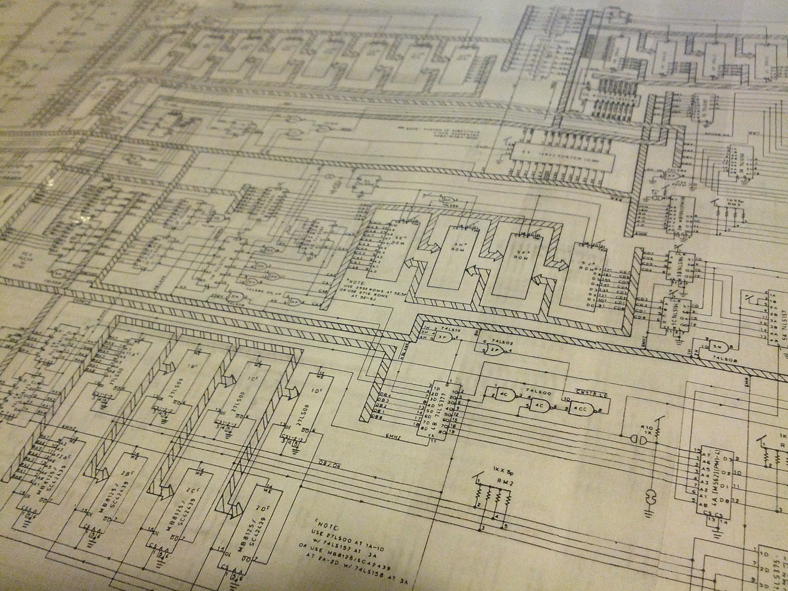
Just some of that discrete logic
Video
Pac Man has less RAM than your old ZX Spectrum, but no Spectrum Pac Man clone ever looked as good as the original. How did they do that? With some clever hardware. The Pac Man video hardware consists two subsystems: tiles and sprites. The tiles cover the entire screen and are stored in a character based array in RAM (think text mode) alongside the corresponding palette entries for each tile. The tiles don’t change much from frame to frame. The text, dots and maze are all drawn as tiles. The sprite hardware is controlled by the sprite registers, implemented as two 74LS89 16 x 4-bit RAMs (yep, that’s a chip with 64 bits of RAM), in the memory mapped IO space. The hardware can draw up to eight 16×16 pixel sprites anywhere on the screen. This means the only animation the CPU has to do is to change the X and Y coordinates of the 5 main game sprites and maybe a few tiles between each frame. This is how a 3MHz CPU manages to drive a fast arcade game.
The video hardware generates the signals necessary to drive the machine’s CRT display (something people in the 20th century used before LCDs). The CRT builds up a video frame line by line, repeating 60 times a second. This would be relatively straightforward if there was a nice tidy video buffer with the RGB values for each pixel available in handy rows for each scanline. But that would take nearly 200k of RAM, over 60 times the amount available. So instead the video hardware has to draw the appropriate part of each tile and sprite from the patterns in the graphics ROMs for the current position of the CRT electron beam in the frame. This takes a lot of very ingenious logic that I’m only just beginning to pick apart. However, the colour system is relatively simple yet gives us a glimpse of some of the tricks used.
The colour of each tile and sprite is determined by 6-bit palette values in RAM. This value is used to index a palette in the palette ROM, then the 2-bit value of each pixel is used to index the colour value for that palette. Then the colour value is used to generate the RGB signal for the monitor. This all sounds bonkers, but when you look at the schematic it makes perfect sense. For example, here’s how the colour value is looked up from the IM5623 256 x 4-bit palette ROM:
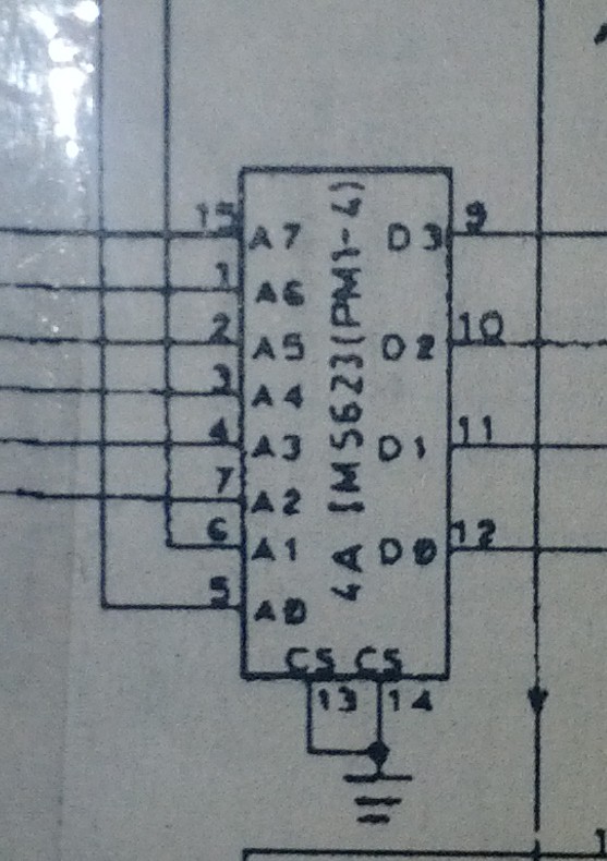
The the upper 6 bits (A2-A7) coming in from the left in the image above provide the index to the palette while the lower two bits (A0-A1) coming in from above from a 2-bit pixel value from the graphics ROM, select the 4-bit colour value within the palette. Now the colour value (D0-D4) has to be turned in to an RGB value for display. Another ROM is used for this:
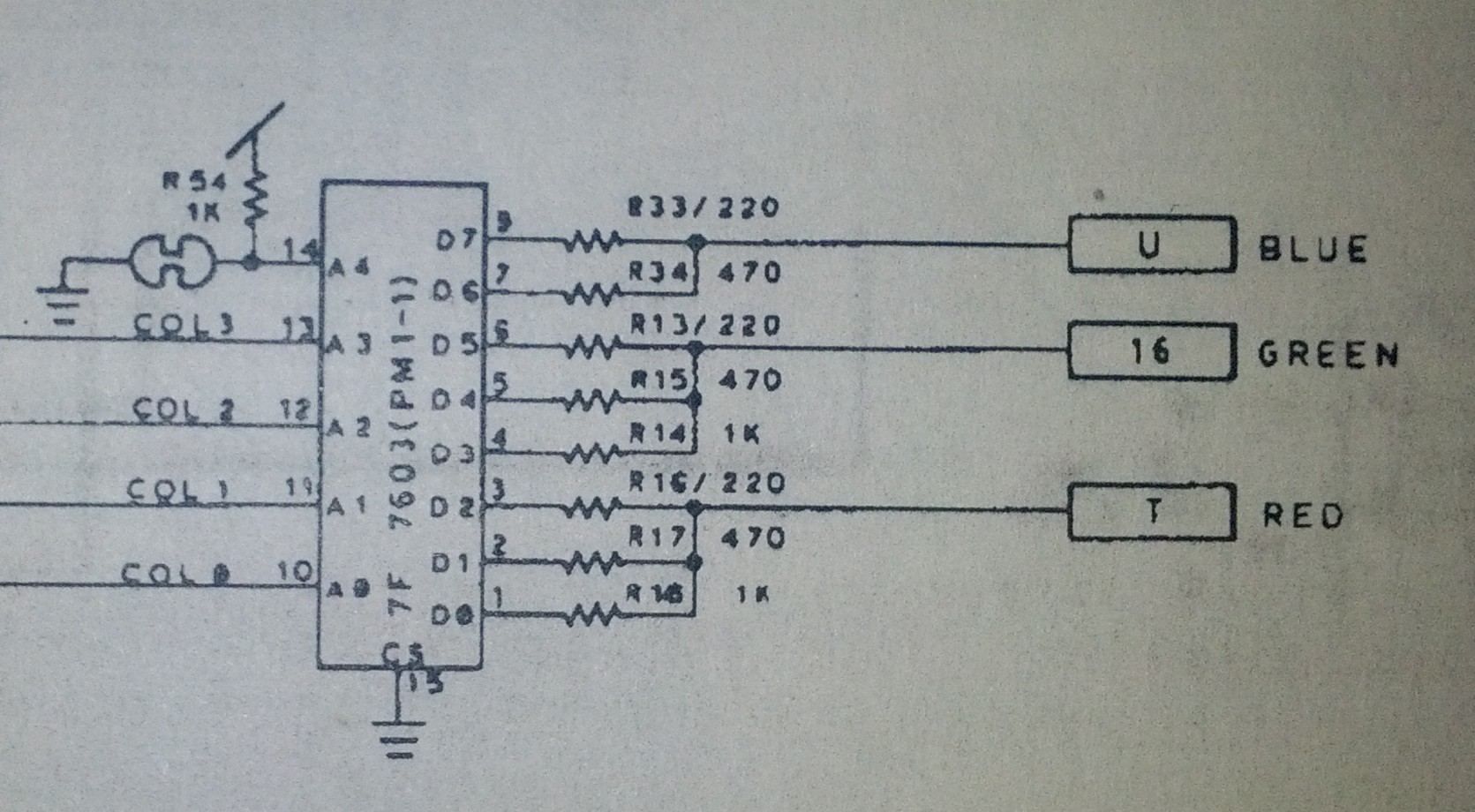
Here the 4-bit colour value (from D0-D4) addresses an 8-bit value in the 32 x 8-bit colour ROM (a 32 byte memory chip – I can’t even find a datasheet for this one) where bits 0-2 are the red component, 3-5 the green and 6-7 blue. Analogue signals are produced from the output for each colour channel by the weighted resistor network and sent to the monitor. Did you ever see a more beautiful D/A converter?
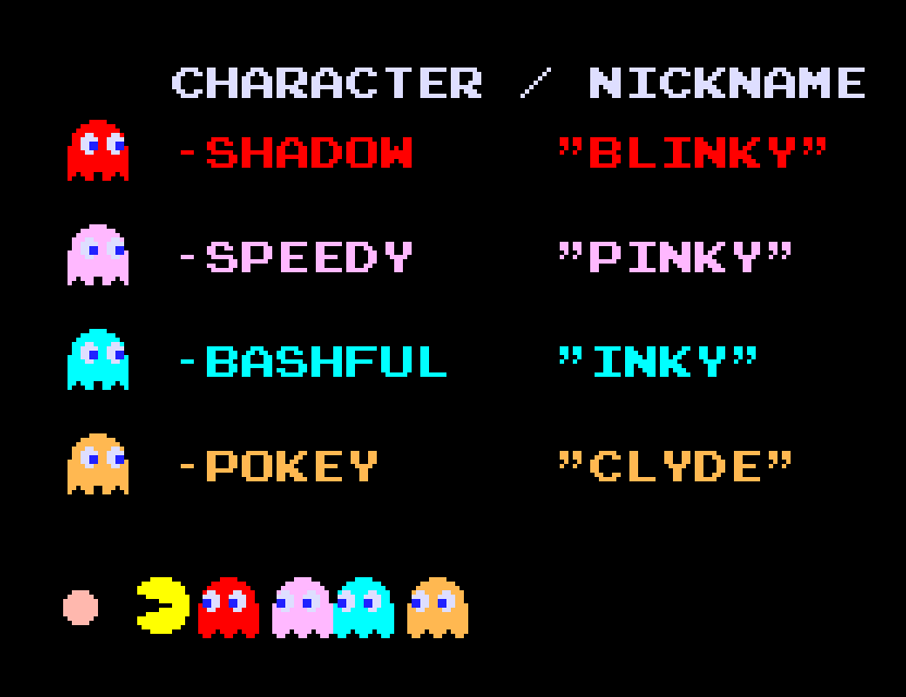
Although the hardware can only display 16 colours and only 4 of those are available per tile or sprite, by using this technique a more interesting palette is possible than the usual primary/secondary colour range of most 8-bit home computers. Take a look at the soft pink of Pinky, the eggshell blue of Inky and Clyde’s light ochre below:
Also the brown of the cherry twig:

Although each sprite can contain 4 colours (2-bits per pixel) in reality you only see three colours displayed because each sprite uses black as a transparent colour. This allows the background tiles to be visible around the edges of the characters:
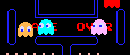
The transparency is achieved by turning off the sprite hardware output when it tries to display a black pixel. As the palette value for black is binary ‘0000’ the ‘off’ signal can be generated very simply with this NAND gate:

Sound
The sound system is pretty clever too. Chris’s PDF explains it very well so I’ll just summarise it here. The sound hardware supports 3 voices on a single mono channel. Each of these voices can select the volume and frequency of one of 8 4-bit output waveforms stored in ROM (each just 32 bytes each). The sound registers (two 74LS89’s like in the sprite hardware) are written to by the CPU over the memory mapped IO space during the 60Hz VBLANK interrupt. The Pac Man sound hardware runs at a 96kHz sample rate so the output from the sound emulator is downsampled to a more conventional 44.1kHz for output by the emulator. The emulator currently doesn’t low pass filter the 96kHz stream though so there could be aliasing in the output.
Summary
I’d definitely recommend anyone with an interest in programming and classic video games to have a go at implementing an emulation. It provides an extra dimension to these games as well as reminding us that the limitations of technology can always be stretched by the application of clever thinking.
You can download the emulator from Github and watch a short video about it here:


